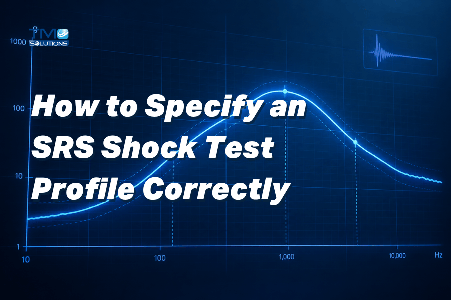
To specify an SRS shock test profile correctly, engineers should define the required response spectrum range, Q value, maximum SRS level, break frequency, rising slope, tolerance, effective wave duration, test direction, payload, fixture stiffness, sensor location and acceptance criteria.
The profile should also state whether the test requires horizontal SRS, vertical SRS, or both.
For accurate system selection, the DUT size, DUT weight, fixture weight, table size and mounting condition must be considered together.
The right SRS shock test system is not selected by maximum g value alone. It is selected by matching the required SRS profile to the system capability, fixture design, measurement setup and real shock environment.
What Is an SRS Shock Test Profile?
An SRS shock test profile defines how a product should respond to a transient shock event across a range of natural frequencies.
SRS stands for Shock Response Spectrum.
Instead of describing shock only as a time-domain pulse, such as 50g / 11ms or 150g / 1.1ms, SRS describes the peak response of a series of single-degree-of-freedom systems across different frequencies. This is important because many real shock events are not simple.
Aerospace separation events, defence equipment shock, pyrotechnic events, impact events, transportation shock and high-frequency mechanical disturbances can contain energy across a wide frequency range.
For engineers, SRS testing answers a more useful question: How will the product respond across the frequency range that matters?
That is different from asking only: What peak acceleration did the machine reach?
Both questions matter, but they are not the same.
Why SRS Profile Specification Matters
An SRS shock test system can only be recommended correctly when the test profile is clearly defined.
If the requirement is incomplete, several problems can happen:
The selected system may not reach the required SRS level.
The table size may not fit the DUT and fixture.
The payload may be underestimated.
The frequency range may not match the real shock environment.
The fixture may introduce unwanted resonance.
The sensor location may not represent the required control point.
The test may pass on the machine but fail to represent the actual application.
The customer may discover system limitations too late in the project.
This is why an SRS inquiry should not only say: “We need a 10,000g SRS shock test system.”
A better inquiry should say: “We need an SRS shock test system for a 200kg total payload, 800 × 800mm table, response spectrum from 50–10,000Hz, Q=10, defined break frequency, specified rising slope, tolerance limits, effective wave duration and required test direction.”
The more complete the profile, the better the recommendation.
SRS Shock Test Profile Checklist
Before requesting an SRS shock test system, engineers should prepare the following information.
| Parameter | What It Means | Why It Matters |
|---|---|---|
| SRS frequency range | The frequency band where the SRS requirement must be met | Defines whether the system must reproduce low, mid or high-frequency shock response |
| Q value | The amplification factor used in the SRS calculation | Affects the sharpness and severity of the response spectrum |
| Maximum SRS level | The highest required acceleration response in g | Helps determine whether the machine has enough energy and control capability |
| Break frequency | The frequency where the SRS curve changes slope or level | Defines the shape of the SRS profile |
| Rising slope | The rate at which the SRS level increases with frequency | Commonly expressed in dB/octave |
| Tolerance | Acceptable deviation from the target SRS curve | Determines whether the test result is considered acceptable |
| Effective wave duration | The useful shock duration used to generate the SRS response | Helps define the energy content and time-domain behaviour |
| Test direction | Horizontal, vertical or combined SRS requirement | Determines whether HSRS, VSRS or both should be considered |
| Table size | Mounting surface required for the DUT and fixture | Ensures the specimen can be mounted safely and correctly |
| Payload | DUT weight plus fixture, adapters, sensors and cables | Affects system performance, control and safety |
| Fixture stiffness | Rigidity of the mounting fixture | Poor fixture design can distort the SRS result |
| Sensor location | Where acceleration is measured or controlled | Determines whether the measured response represents the required point |
| Acceptance criteria | Pass/fail rules for the test | Prevents ambiguity during FAT, testing and reporting |
Key Parameters Engineers Need to Define
1. Define the SRS Frequency Range
The frequency range tells the test system which part of the response spectrum must be reproduced.
For aerospace and defence shock, high-frequency response is often important because small structures, circuit boards, connectors, relays, sensors and internal components may be sensitive to short-duration transient events.
A common SRS range may extend into several thousand hertz. In some aerospace or pyroshock-related cases, requirements may extend to 10,000Hz or higher depending on the specification.
When defining the frequency range, engineers should clarify:
Start frequency
End frequency
Frequency resolution
Whether the requirement is based on a standard, measured field data or a customer specification
Whether the frequency band includes resonance-sensitive parts of the product
Whether high-frequency response is critical to the application
For example: Response Spectrum: 50–10,000Hz
This tells the supplier that the system must be evaluated across that frequency band, not only at one acceleration level.
2. Confirm the Q Value
The Q value is one of the most important parameters in SRS testing. In simple terms, Q describes how strongly the theoretical single-degree-of-freedom systems respond at their natural frequencies.
A higher Q value means less damping and sharper resonance response.
A lower Q value means more damping and a broader, less sharp response.
Many SRS profiles use Q=10, especially when a specification or standard does not state another value. However, engineers should never assume the Q value without checking the actual requirement.
When sending an SRS profile, include:
Required Q value
Whether Q is specified by the standard or customer
Whether the same Q applies across the full frequency range
Any damping assumptions used in the test profile
Example:
Q value: 10
This single number affects how the SRS is calculated and evaluated.
3. Specify the Maximum SRS Level
The maximum SRS level is the highest acceleration response required in the SRS curve. This may be expressed in g. However, maximum SRS alone is not enough to specify a system.
For example, two systems may both claim high maximum SRS capability, but the real fit depends on:
Frequency range
Table size
Payload
Direction
Fixture
Effective wave duration
Tolerance
Energy required to meet the profile
Whether the SRS level must be achieved over the full required range
When contacting TMC, provide the complete SRS curve if available, not only the peak value.
Example:
Max. SRS: 10,000g
Useful, but incomplete unless paired with frequency range, Q value, payload, table size and tolerance.
4. Define the Break Frequency
The break frequency is the point where the SRS profile changes behaviour.
For example, the SRS curve may rise at a defined slope up to a certain frequency, then become flat or follow a different slope. Break frequency helps define the actual shape of the required SRS profile.
Engineers should provide:
Break frequency range
Exact break point if known
Whether the break frequency is fixed or adjustable
Whether the test standard defines the break frequency
Whether the SRS curve has one or multiple break points
Example:
Break Frequency: 250–2,000Hz
This information helps determine whether the SRS system can reproduce the profile shape with the required control.
5. State the Rising Slope
The rising slope describes how quickly the SRS level increases with frequency. It is often expressed in dB/octave.
This parameter matters because it influences the energy distribution across the frequency band. A profile with a steep rising slope may require different system performance compared with a flatter profile.
Engineers should provide:
Rising slope in dB/octave
Frequency range where the slope applies
Whether the slope is defined by the standard or customer
Whether there is an upper plateau after the rising section
Example:
Rising Slope Range: 6–9dB/oct
This gives the engineering team a clearer picture of the SRS curve shape.
6. Define the Tolerance Limits
Tolerance defines how close the measured response must be to the target SRS curve. Without tolerance limits, it is difficult to judge whether the test has passed. Tolerance may vary by frequency range. For example, the tolerance below a certain frequency may be different from the tolerance above that frequency.
Engineers should clearly state:
Upper tolerance
Lower tolerance
Frequency-dependent tolerance
Whether tolerance is based on the standard, customer requirement or internal qualification rule
Whether tolerance applies to all axes or only one direction
How many test runs must meet the tolerance
Example:
Tolerance: fn ≤ 3kHz: ±6dB; fn > 3kHz: +9 / -6dB
This gives both the customer and supplier a shared definition of acceptable performance.
7. Define the Effective Wave Duration
Effective wave duration describes the useful time-domain shock duration used to generate the required SRS. Although SRS is evaluated in the frequency domain, the time-domain waveform still matters. A test pulse that is too short, too long or poorly controlled may not create the required spectrum correctly.
Engineers should provide:
Maximum effective wave duration
Adjustable duration requirements
Time-domain limitations
Whether the duration is linked to a standard or customer profile
Whether the system must produce repeatable effective wave duration across multiple runs
Example:
Max. Duration of Effective Wave: ≤20ms, adjustable
This helps confirm whether the selected SRS shock test system can generate the required transient event.
8. Choose the Test Direction: Horizontal, Vertical or Both
SRS shock testing may be required in the horizontal direction, vertical direction or both. The direction matters because the real product installation may experience shock from a specific orientation.
For example:
A mounted aerospace electronics box may need vertical SRS testing.
A defence component may require horizontal SRS testing.
A component installed in a complex system may need testing in multiple directions.
Some qualification programs may require vertical and horizontal SRS to complete the test matrix.
TMC provides both horizontal and vertical SRS shock testing solutions.
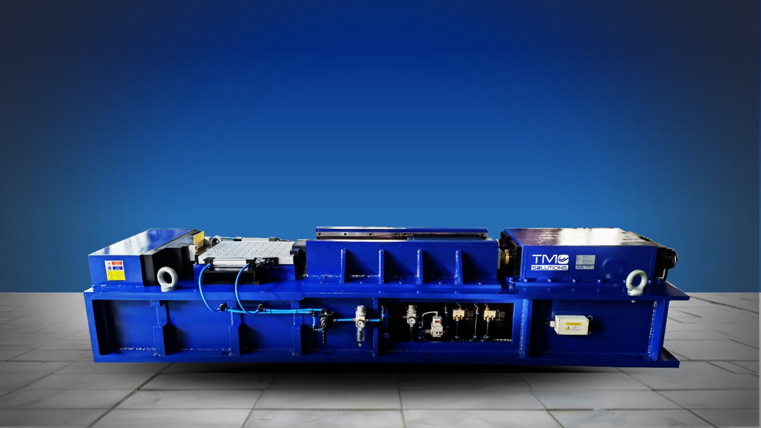
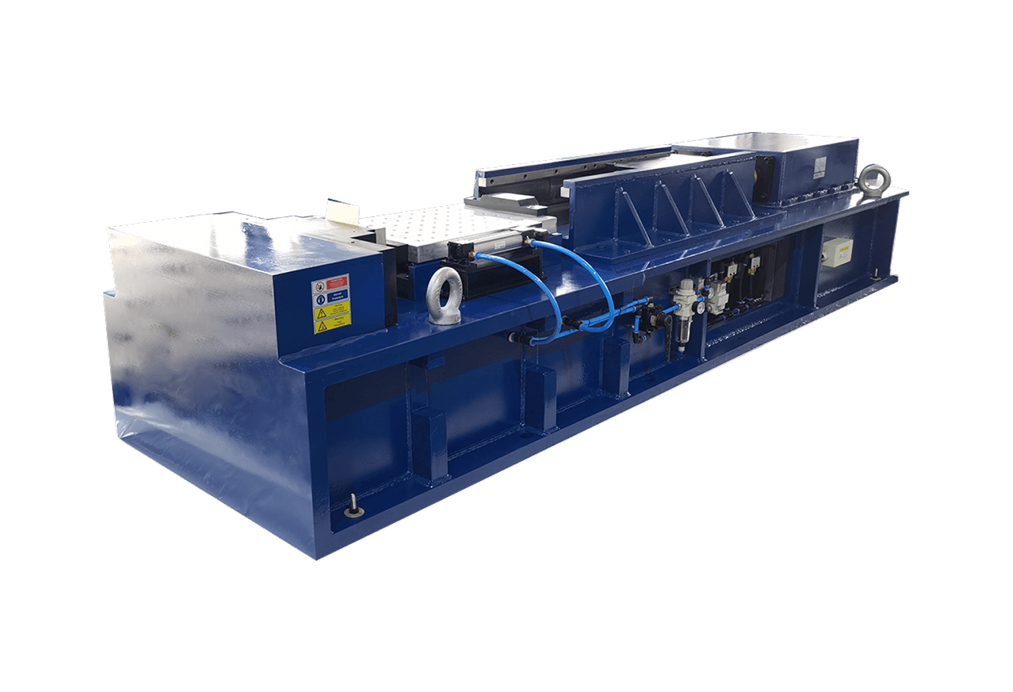
For horizontal SRS requirements, engineers can review the HSRS Series Pneumatic Shock Response Spectrum Test System
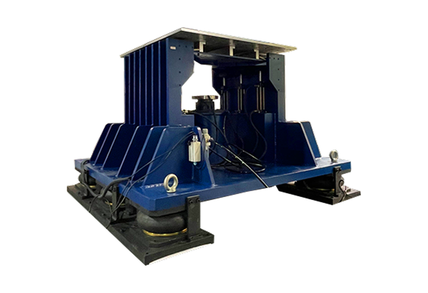
For vertical SRS requirements, engineers can review the VSRS Series Pneumatic Shock Response Spectrum Test System
In some cases, vertical and horizontal SRS testing can be combined to provide a more complete evaluation.
9. Confirm Table Size
Table size determines whether the DUT and fixture can be mounted correctly. This is not just a space question.
Table size affects:
Fixture layout
Bolt pattern
DUT orientation
Centre of gravity
Sensor placement
Cable routing
Safety clearance
Test repeatability
A larger table may be required when the test item is wide, heavy, irregularly shaped or requires a complex fixture.
Example:
Table Size: 800 × 800mm
This helps TMC understand whether the required SRS system has the right mounting surface for the application.
10. Calculate the Real Payload
Payload is one of the most common sources of misunderstanding in shock test system selection. The payload is not only the product being tested.
It should include:
DUT weight
Fixture weight
Mounting plate
Adapters
Sensors
Cables
Protective tooling
Any accessories mounted on the table
A 120kg product may become a 180kg or 200kg test load after the fixture and accessories are added.
This matters because payload affects:
Achievable SRS level
Frequency response
Table movement
Braking requirement
Safety margin
Repeatability
System sizing
Before requesting a system recommendation, engineers should calculate the full mounted test mass.
Example:
Max. Load: 200kg
This should be understood as total mounted load, not only the DUT mass.
11. Review Fixture Stiffness
In SRS shock testing, the fixture is not a secondary detail. A poor fixture can change the test result. If the fixture is too flexible, too heavy, poorly aligned or not representative of the real installation, it may introduce unwanted resonance or absorb energy in a way that distorts the measured SRS.
A good fixture should:
Hold the DUT securely
Match the real mounting condition as much as possible
Have sufficient stiffness
Avoid unnecessary resonance
Keep the DUT aligned with the test direction
Allow safe sensor placement
Allow repeatable installation
Avoid loose parts or unsupported structures
For aerospace, defence, electronics and high-reliability products, fixture design should be discussed early. A strong SRS machine cannot compensate for a weak or unrealistic fixture.
12. Define Sensor Location and Measurement Points
SRS testing depends on the quality of the measurement. The sensor location should be defined clearly.
Engineers should specify:
Control accelerometer location
Response accelerometer location, if required
Measurement axis
Sensor mounting method
Cable routing
Data acquisition settings
Sampling frequency
Filtering requirements
Calibration requirements
Whether measurement is taken at the table, fixture or DUT
This is important because the SRS measured at the table may not be identical to the response measured at the DUT. If the customer specification defines a control point, that location should be communicated before system selection.
13. Clarify Acceptance Criteria
Acceptance criteria define whether the SRS test result is considered successful.
Before testing, both the customer and supplier should understand:
Required SRS curve
Tolerance limits
Number of test runs
Test direction
Measurement point
Pass/fail rule
Data format
Reporting requirement
Whether functional testing is needed before and after shock
Whether visual inspection is required after the test
For example, an aerospace electronics module may need to pass the SRS profile and remain electrically functional after the test.
A mechanical assembly may need to show no cracks, loosening, deformation or permanent damage.
A defence system may need both structural and functional verification.
Acceptance criteria prevent confusion during factory acceptance testing, qualification testing and final reporting.
SRS Profile Example for an Engineering Inquiry
Below is an example of how an engineer could describe an SRS shock test requirement when contacting TMC.
| Required Information | Example |
|---|---|
| Application | Aerospace electronics module |
| Test direction | Horizontal SRS |
| Table size | 800 × 800mm |
| Total payload | 200kg including fixture |
| Max SRS | 10,000g |
| Response spectrum range | 50–10,000Hz |
| Q value | 10 |
| Break frequency | 250–2,000Hz |
| Rising slope | 6–9dB/oct |
| Tolerance | fn ≤ 3kHz: ±6dB; fn > 3kHz: +9 / -6dB |
| Effective wave duration | ≤20ms, adjustable |
| Fixture | Rigid fixture, customer-supplied or designed with TMC support |
| Sensor location | Control accelerometer on fixture/table interface |
| Acceptance criteria | SRS curve within tolerance; DUT remains functional after test |
| Required support | System recommendation, fixture review, FAT before shipment |
This type of request gives TMC’s engineering team enough information to review the test profile and recommend a suitable system.
HSRS, VSRS or VASII: Which System Should Engineers Consider?
SRS shock testing does not always require the same system. The correct choice depends on the test direction, waveform, severity and application.
| Requirement | Best-Fit TMC System Type | Why |
|---|---|---|
| Horizontal SRS shock testing | HSRS Series | Designed for horizontal Shock Response Spectrum testing |
| Vertical SRS shock testing | VSRS Series | Designed for SRS requirements in the vertical direction |
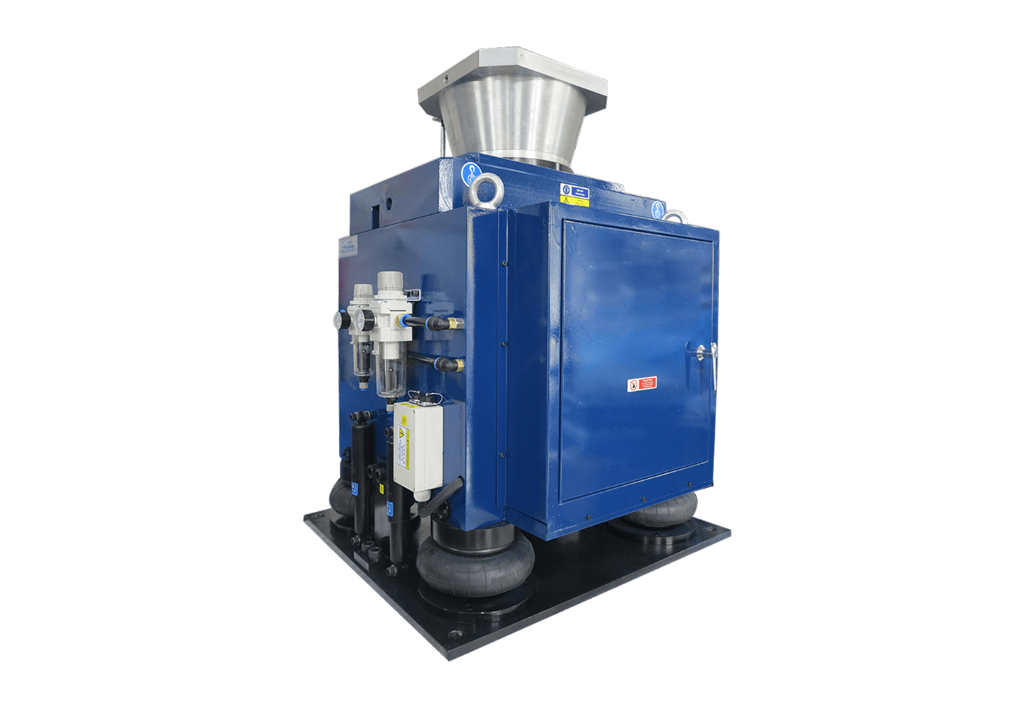
| Conventional shock pulse testing | VASII Series | Suitable for half-sine, post-peak sawtooth and trapezoidal wave shock testing |
| Full product comparison | TMC Products page | Useful when the customer is still comparing shock, vibration, drop, centrifuge or motion systems |
| Unclear requirement | Contact TMC | Engineering review is needed before system selection |
HSRS Series Pneumatic Shock Response Spectrum Test System
VSRS Series Pneumatic Shock Response Spectrum Test System
VASII Series Pneumatic Vertical Shock Test System
When to Use an SRS Shock Test System
Use an SRS shock test system when the shock event is complex, high-frequency, transient or difficult to represent with a simple classical pulse.
SRS testing is especially useful for:
Aerospace components
Defence electronics
Avionics
Satellite components
Communication equipment
Optical assemblies
Navigation equipment
Control modules
PCB assemblies
Products exposed to pyroshock-like events
Products sensitive to resonance
Mission-critical products where failure is costly or unsafe
SRS testing is often more useful than classical shock when engineers need to understand response across frequency, not only one peak acceleration value.
When Classical Shock Testing May Be Enough
SRS testing is not always required.
Classical shock testing may be enough when the standard or test objective specifies a time-domain pulse such as:
Half-sine
Trapezoidal
Post-peak sawtooth
Defined acceleration and duration
General impact resistance
Packaging shock
Handling shock
Transportation shock
In these cases, a conventional shock test system such as the VASII Series Pneumatic Vertical Shock Test System may be more suitable.
The right question is: Does the test requirement define a simple pulse, or does it define a response spectrum?
If the requirement is response-spectrum based, SRS testing should be considered.
If the requirement is pulse-based, conventional shock testing may be appropriate.
Real Application Example: Specifying SRS for Aerospace Electronics
An aerospace electronics manufacturer needs to qualify a control module before deployment.
The module includes:
PCB assemblies
Connectors
Solder joints
Internal wiring
Metal housing
Mounting brackets
Interface ports
Sensor components
The customer requirement includes a high-frequency shock response profile. The test is not simply a half-sine pulse. The engineering team needs to confirm that the module can withstand transient shock energy across a defined frequency range.
Before contacting TMC, the engineer prepares:
DUT dimensions
DUT weight
Fixture concept
Required test direction
SRS curve
Frequency range
Q value
Break frequency
Rising slope
Tolerance
Effective wave duration
Functional test requirements
Reporting format
FAT requirements before shipment
After reviewing the profile, TMC can determine whether the requirement is more suitable for an HSRS horizontal SRS system, VSRS vertical SRS system, or another customized shock test setup.
This process helps avoid oversizing, undersizing or selecting a system that cannot reproduce the required profile with the real payload.
Common Mistakes When Specifying an SRS Shock Test Profile
-
Maximum g is important, but it does not define the full SRS requirement.
A complete profile needs frequency range, Q value, curve shape, break frequency, slope, tolerance and duration.
-
A fixture can add significant mass.
If engineers provide only the DUT weight, the system may be incorrectly sized.
-
Horizontal and vertical SRS requirements are not the same.
The direction should be defined early because it affects system selection.
-
Fixture stiffness affects the SRS result.
A flexible or unrealistic fixture can create misleading data.
-
The measured SRS depends on where the accelerometer is mounted.
Sensor location should be part of the test definition.
-
A statement like “100g / 6ms” describes a time-domain pulse.
An SRS requirement needs a response spectrum curve or frequency-domain specification.
-
Tolerance, pass/fail rules and reporting requirements should be clear before testing starts.
Questions to Prepare Before Contacting TMC
To help TMC recommend the right SRS shock test system, prepare the following:
What product or component will be tested?
What industry or application is it for?
What is the DUT size?
What is the DUT weight?
What is the estimated fixture weight?
What is the total mounted payload?
What table size is required?
Is the test horizontal, vertical or both?
What is the required SRS frequency range?
What is the Q value?
What is the maximum SRS level?
What is the break frequency?
What is the rising slope?
What tolerance is required?
What effective wave duration is required?
Where should the control sensor be mounted?
Does the DUT need to be powered during the test?
Is functional testing required before and after shock?
What standard or customer specification applies?
Is FAT required before shipment?
This information helps TMC move from general discussion to a useful engineering recommendation.
External Standards and References
SRS testing is often used in aerospace and defence environments where shock events are complex and frequency response matters.
Useful external references:
NASA JSC 65829, Loads and Dynamics Requirements for Spaceflight Hardware https://standards.nasa.gov/sites/default/files/standards/JSC/B/0/Historical/JSC-65829-Loads-Dyn_Req_for_SF_Hardware-RevB_signed_page2_footer_corrected.pdf
NASA MIL-STD-810 Environmental Engineering Considerations and Laboratory Tests https://standards.nasa.gov/standard/NASA/MIL-STD-810
DLA ASSIST Quick Search, MIL-STD-810 Document Details https://quicksearch.dla.mil/qsDocDetails.aspx?ident_number=35978
Important note: standards and customer specifications should always be reviewed carefully for the exact test method, tolerance, fixture requirement and acceptance criteria. TMC can help recommend a test system, but the final test profile should follow the applicable program or customer requirement.
FAQ: SRS Shock Test Profile Specification
-
Engineers should provide the SRS frequency range, Q value, maximum SRS level, break frequency, rising slope, tolerance, effective wave duration, test direction, table size, total payload, fixture details, sensor location and acceptance criteria.
-
Engineers define an SRS shock test profile by describing the target response spectrum across a frequency range. The profile normally includes Q value, acceleration level, curve shape, break frequency, slope, tolerance and test direction.
-
Q=10 is a common dynamic amplification factor used in SRS calculations. It represents the damping assumption used for the theoretical single-degree-of-freedom systems in the SRS analysis.
-
No. Maximum g is only one parameter. Engineers must also define frequency range, Q value, break frequency, slope, tolerance, effective duration, payload, table size, fixture stiffness and measurement location.
-
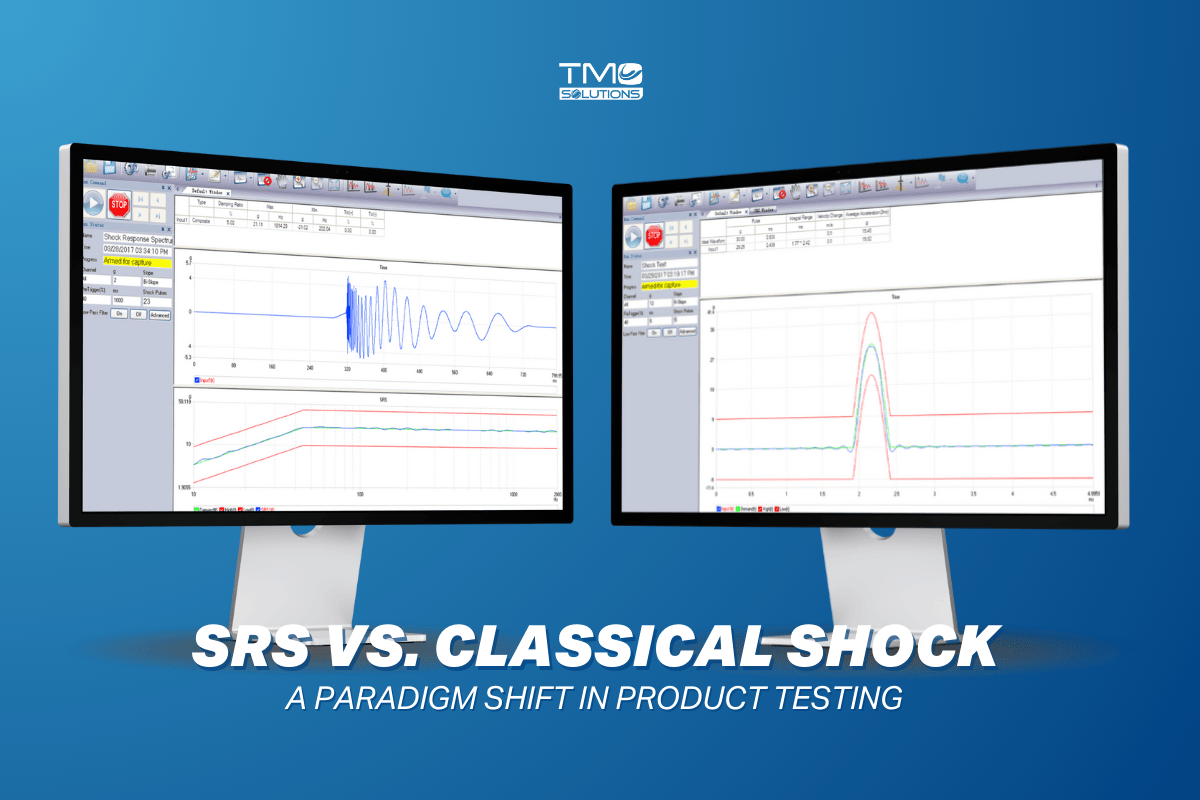
Classical shock testing usually defines a time-domain pulse such as half-sine, trapezoidal or sawtooth. SRS testing defines how the product responds across a frequency spectrum after a transient shock event.
-
Horizontal SRS testing should be used when the required shock direction is horizontal or when the product’s real installation condition is mainly exposed to lateral shock. TMC’s HSRS Series is designed for horizontal SRS testing.
-
Vertical SRS testing should be used when the required shock direction is vertical or when the qualification program specifies vertical response-spectrum shock. TMC’s VSRS Series is designed for vertical SRS testing.
-
Fixture stiffness matters because the fixture can change the measured response. A weak or flexible fixture may introduce unwanted resonance, absorb energy or create a test condition that does not represent the real installation.
-
The accelerometer should be mounted at the specified control or measurement location defined by the test standard or customer requirement. This may be on the table, fixture or DUT interface, depending on the test objective.
-
No. SRS system suitability depends on frequency range, maximum SRS level, payload, table size, test direction, fixture, effective duration and tolerance. Each profile should be reviewed before selecting the system.
-
Customers should send the test standard or SRS curve, DUT size and weight, fixture weight, total payload, table size, test direction, Q value, frequency range, maximum SRS level, break frequency, slope, tolerance, effective wave duration and acceptance criteria.
Final Recommendation
A correct SRS shock test profile should describe the full response requirement, not only the peak acceleration.
For engineers, the most important information includes:
Frequency range
Q value
Maximum SRS level
Break frequency
Rising slope
Tolerance
Effective wave duration
Test direction
Table size
Total payload
Fixture stiffness
Sensor location
Acceptance criteria
Once these parameters are clear, TMC can help determine whether the application requires an HSRS horizontal SRS test system, VSRS vertical SRS test system, VASII conventional shock system, or a customized shock testing solution.
Need help choosing the right SRS shock test system?
Get a system recommendation from our engineering team.
You may be interested also in: