Shock Test Systems for Aerospace Components
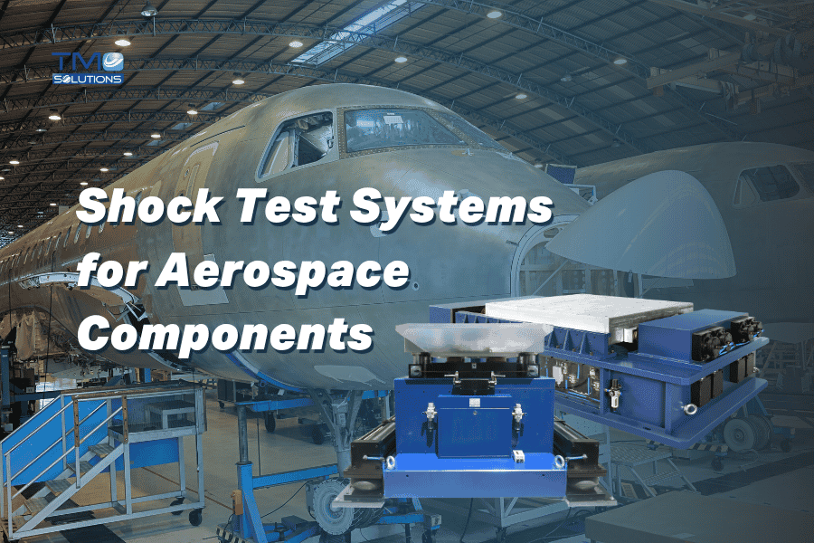
Shock Test Systems for Aerospace Components: Key Features Engineers Should Compare
The key features of shock test systems for aerospace components include pulse accuracy, waveform capability, SRS performance, payload capacity, fixture compatibility, braking control, safety protection, measurement accuracy, and repeatability.
For aerospace applications, engineers should not choose a shock test system based only on maximum acceleration.
They should compare whether the system can reproduce the required shock environment, hold the component securely, protect operators, capture reliable data, and support the relevant test standards.
For conventional mechanical shock tests, vertical or horizontal shock systems may be suitable.
For high-frequency, complex, or pyrotechnic-like shock events, an SRS shock test system is often the better fit.
Why Aerospace Shock Testing Needs Careful System Selection
Aerospace components often operate in conditions where sudden mechanical shock can affect performance, safety, and mission reliability.
Shock events may occur during:
Launch
Landing
Separation events
Transportation
Handling
Installation
Turbulence-related mechanical loading
Equipment deployment
Emergency operation
Defence or mission-critical use
For aerospace engineers, shock testing is not simply about proving that a part can survive one impact.
It is about understanding how the component behaves under a controlled mechanical event that may affect structure, electronics, connectors, fasteners, seals, sensors, optics, or internal assemblies.
A weak solder joint, loose connector, cracked bracket, shifted sensor, or damaged housing may not be visible during inspection. But under mechanical shock, these weaknesses can become measurable failure risks.
That is why choosing the right shock test system matters.
The wrong system may produce a test that looks valid but does not represent the actual aerospace shock environment. The right system helps engineers reproduce the required event, collect useful data, improve the design, and reduce the risk of failure after deployment.
What Is a Shock Test System for Aerospace Components?
A shock test system is a reliability testing machine used to reproduce sudden mechanical impact or acceleration events under controlled laboratory conditions.
For aerospace components, shock testing is commonly used to evaluate whether a product can withstand mechanical stress without losing structural integrity, electrical function, alignment, or safety performance.
Aerospace shock testing may involve different pulse types, including:
Half-sine shock
Trapezoidal shock
Sawtooth shock
Post-peak sawtooth shock
Shock response spectrum, or SRS
High-g acceleration events
Directional shock testing
Repeated bump or collision testing
Custom shock profiles
The right system depends on the component, payload, test direction, waveform, acceleration level, duration, frequency content, and standard being followed.
Key Features Engineers Should Compare
1. Shock Pulse Capability
The first feature engineers should compare is the system’s ability to generate the required shock pulse.
Different aerospace components may require different shock pulse shapes. A half-sine pulse may be used for general mechanical shock validation. A trapezoidal pulse may be required where the force profile needs a more constant plateau. A sawtooth or post-peak sawtooth pulse may be useful when the test condition has a fast rise or decay pattern.
For more complex aerospace shock environments, especially those involving high-frequency transient response, engineers may need SRS testing.
A useful shock test system should allow the test team to select, control, and repeat the required pulse type accurately.
2. SRS Testing Capability
SRS, or Shock Response Spectrum, is especially important in aerospace testing because many aerospace shock events are not simple single-pulse impacts.
A component may experience a short-duration event with broad frequency content. The important question is not only the peak acceleration. It is also how the component responds across a frequency range.
SRS testing helps engineers understand how a product may respond to complex transient shock events.
This is important for:
Aerospace electronics
Avionics
Sensors
Optical equipment
Satellite components
Defence systems
Control modules
Communication equipment
High-value mission-critical assemblies
When comparing shock test systems for aerospace components, engineers should ask:
Can the system generate the required SRS profile?
Can it control the frequency response accurately?
Can it support the required acceleration level and duration?
Can it repeat the profile consistently?
Can the measurement system capture the real response of the DUT?
For aerospace applications where complex transient shock matters, SRS capability can be one of the most important selection criteria.
3. Payload Capacity
Payload capacity must match the real test article, fixture, sensors, and mounting hardware.
A common mistake is to calculate only the mass of the component. In reality, engineers also need to include:
Fixture mass
Mounting plates
Adapters
Cables
Sensors
Protective structures
Any required interface tooling
A shock system that is suitable for a small electronic module may not be suitable for a larger aerospace assembly.
Payload capacity also affects pulse quality. If the payload is too heavy or poorly mounted, the system may not reproduce the required waveform accurately.
Before choosing a shock test system, engineers should define the full test mass and confirm whether the system can perform the required pulse with that load.
4. Test Direction: Vertical, Horizontal, or Multi-Direction
Aerospace components rarely experience shock from only one ideal direction.
Depending on the application, the component may need testing in vertical, horizontal, or multiple axes.
A vertical shock test system may be suitable for many standard mechanical shock requirements.
A horizontal shock test system may be needed when the real shock direction is lateral.
In some cases, engineers may require both vertical and horizontal systems to complete testing across multiple directions.
For aerospace components, this is important because mounting orientation can affect failure behaviour. A connector may survive one direction but fail in another. A bracket may be strong vertically but weak under lateral impact. A sensor may shift differently depending on the direction of the shock.
When comparing systems, engineers should ask:
Which directions must be tested?
Can the fixture reproduce the real mounting condition?
Does the system support the required test orientation?
Will the same component need testing in several axes?
5. Fixture Compatibility
Fixture design is one of the most important parts of aerospace shock testing.
Even a high-quality shock machine can produce poor data if the fixture is not suitable.
The fixture must hold the component securely while preserving the intended boundary condition. It should not introduce unwanted resonance, excessive flexibility, or unrealistic mounting behaviour.
For aerospace components, fixture design should consider:
Actual installation orientation
Mounting points
Centre of gravity
Structural stiffness
Safety margins
Sensor placement
Cable routing
Repeatability between tests
Ease of specimen installation
Protection of delicate interfaces
A good shock test system should support custom fixture integration, especially for aerospace components with complex shapes or strict mounting requirements.
6. Waveform Repeatability
Repeatability is critical in aerospace testing.
Engineers often need to compare test results across multiple samples, design revisions, or qualification stages. If the shock system cannot reproduce the pulse consistently, the test data becomes less useful.
When comparing shock test systems, engineers should check:
Pulse repeatability
Table movement control
Braking performance
Guide system stability
Measurement consistency
Control accuracy
Operator setup repeatability
Repeatable shock testing allows engineers to make better decisions about design strength, production consistency, and product readiness.
7. Braking and Anti-Secondary Shock Control
In shock testing, the main pulse is not the only concern.
Secondary shock can affect the test result and may expose the component to an unintended event.
A good shock test system should include braking or anti-secondary shock control to prevent unwanted additional impacts after the main pulse.
This is important for aerospace components because unintended secondary events may damage the test article, distort the results, or create a test condition that does not match the required standard.
Engineers should compare how each system controls table movement after the shock event and whether it can prevent unwanted rebound or secondary impact.
8. Measurement and Data Acquisition
Aerospace shock testing requires reliable data.
The system should support accurate measurement of acceleration, pulse shape, duration, and response. For SRS testing, the system should also support appropriate data acquisition and analysis across the required frequency range.
A complete shock test setup may include:
Shock machine
Controller
Measurement instrument
Accelerometers
Waveform generator
Compressor or hydraulic power system, depending on machine type
Computer control
Data acquisition system
Safety monitoring
Engineers should not treat measurement as an afterthought. The value of shock testing depends on the quality of the data collected.
9. Safety Protection
Aerospace shock testing can involve high energy, heavy fixtures, large payloads, and sudden motion.
Safety features should be reviewed carefully before choosing a system.
Important safety features may include:
Safety barriers
Emergency stop
Door locks
Guarding
Table locking devices
Hydraulic or pneumatic safety protection
Fixture safety checks
Operator access control
Warning labels
Safe maintenance access
Floor shock reduction measures
Safety is especially important when testing high-value aerospace components or large assemblies where failure during the test could create debris, movement, or equipment damage.
10. System Automation and Ease of Operation
Automation helps improve consistency and reduce operator error.
For aerospace test labs, this can be important when running repeated tests, multiple specimens, or qualification programs that require careful documentation.
Useful automation features may include:
Controlled table lifting
Computer-based parameter setting
Automated pulse generation
Data recording
Repeatable setup workflows
Safety interlocks
Test sequence control
Alarm monitoring
Ease of operation does not mean the test is simple. It means the system helps the operator run complex testing more consistently.
11. Standard and Test Profile Compatibility
Aerospace components may need to meet internal company standards, customer specifications, defence standards, or environmental test standards such as MIL-STD-810.
Before selecting a shock test system, engineers should confirm:
Required acceleration level
Shock duration
Pulse shape
Number of shocks
Test direction
Fixture requirements
Measurement method
Acceptance criteria
Reporting requirements
SRS profile, if applicable
The system should be selected around the actual test profile, not only general equipment capacity.
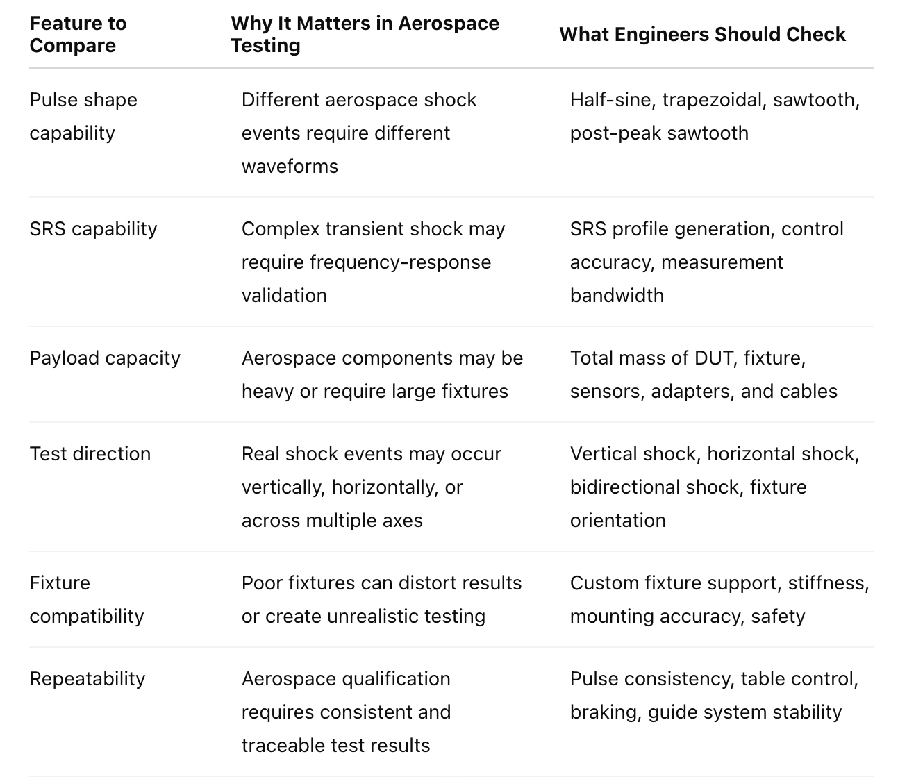
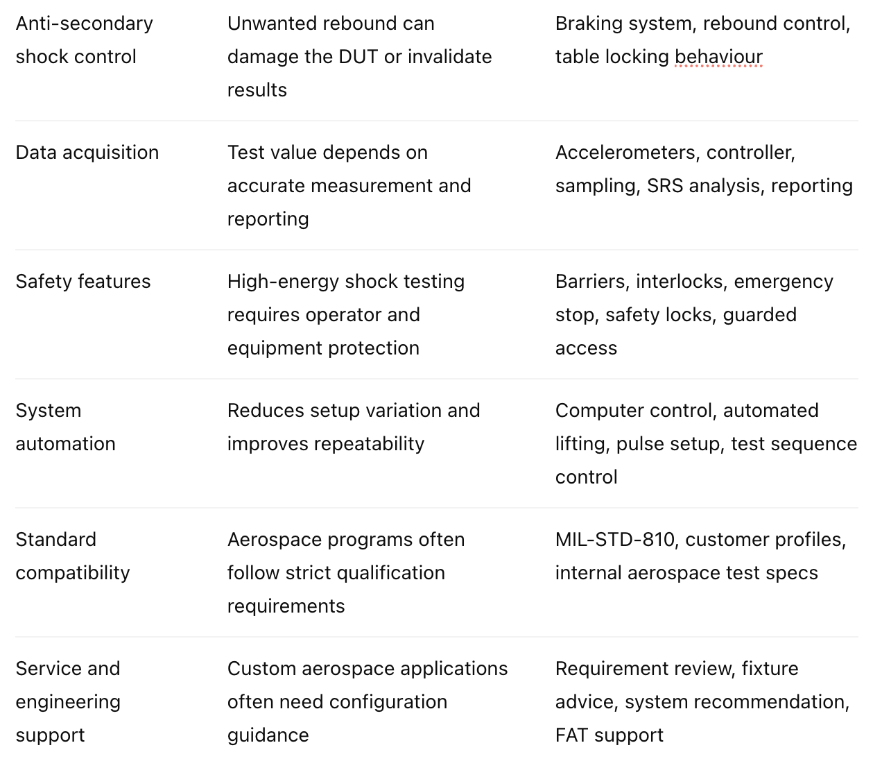
Comparison Table: Key Features of Aerospace Shock Test Systems
TMC Shock Test Systems for Aerospace Applications
TMC Solutions manufactures several types of shock and reliability test systems that can support aerospace-related testing requirements.
The right selection depends on the test objective.
VASI Series Pneumatic Vertical Shock Test System
The VASI Series is suitable for vertical mechanical shock testing where the test requirement involves controlled impact in the vertical direction.
It can be considered for aerospace components that need conventional mechanical shock validation, especially when the required test direction is vertical.
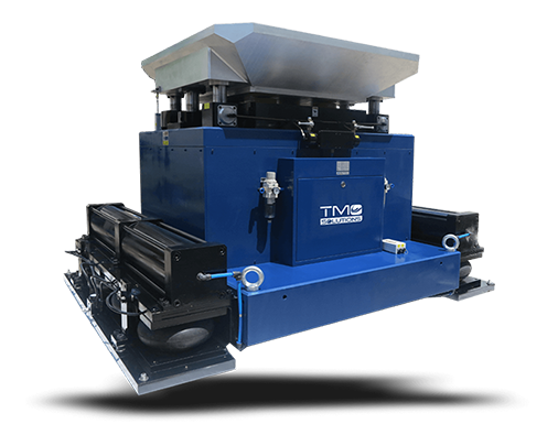
VASII Series Pneumatic Vertical Shock Test System
The VASII Series is designed for conventional shock waveforms such as half-sine, trapezoidal, and post-peak sawtooth shock.
This makes it relevant for aerospace teams that need controlled shock pulse generation with repeatable operation and strong waveform flexibility.
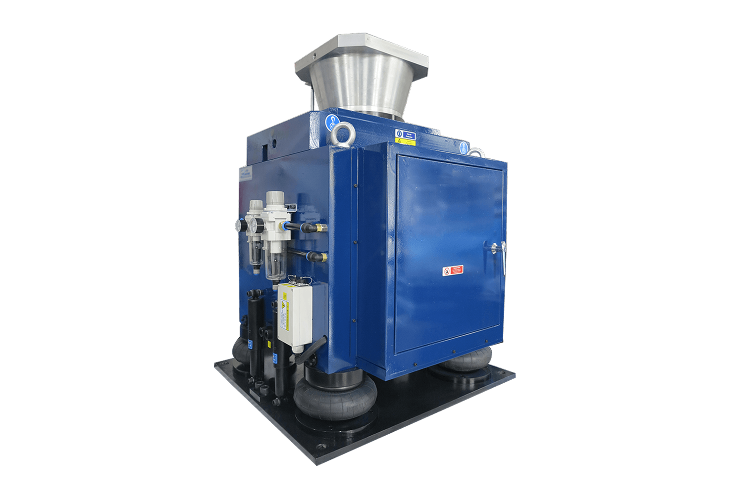
HAS Series Pneumatic Horizontal Shock Test System
The HAS Series is suitable when the shock direction is horizontal.
This can be important for aerospace components where the real installation or transport shock condition is lateral rather than vertical.
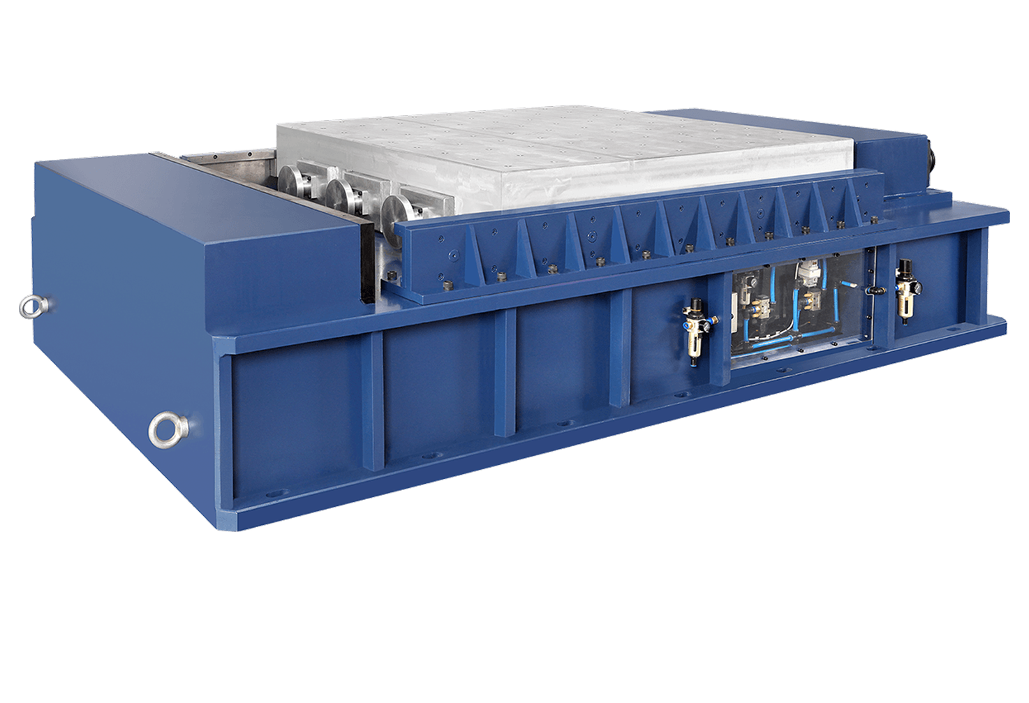
DVAS Series Bidirectional Pneumatic Vertical Shock Test System
The DVAS Series is useful when the test requirement involves bidirectional vertical shock.
This can support applications where the component must be validated under upward and downward shock conditions.

HSRS Series Pneumatic Shock Response Spectrum Test System
The HSRS Series is relevant for aerospace applications requiring shock response spectrum testing.
SRS testing is important when the shock environment is complex and engineers need to understand how the component responds across a frequency range.
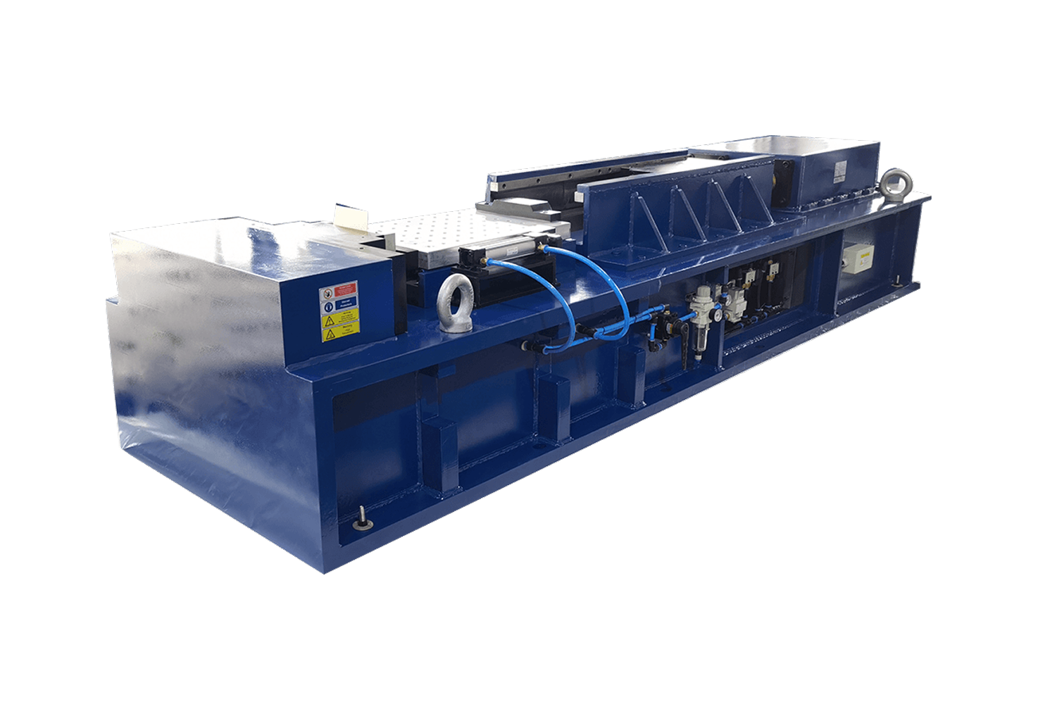
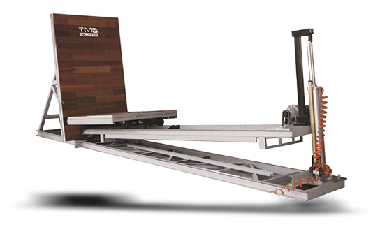
MHI Bevel Shock Test System
The MHI Bevel Shock system may be considered for specific impact simulation requirements where the test setup requires a bevel shock configuration.
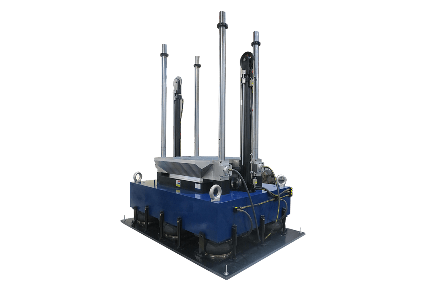
MS Series Hydraulic Shock Test System
The MS Series Hydraulic Shock Test System is relevant when high-force hydraulic shock testing is required, especially for heavier payloads or applications requiring strong impact simulation.
Supporting Systems: Centrifuge, Rate Tables, Motion Simulators, and Drop Testing
Aerospace qualification may require more than one type of mechanical reliability test.
Depending on the component and application, engineers may also need:
Centrifuge testing for constant acceleration and high-g validation
Rate tables for rotational or angular motion testing
Motion simulators for controlled movement conditions
Drop testing for packaging, handling, and transport validation
Vibration testing for repeated dynamic loads
When to Use Each Shock Test System
Use a Vertical Shock Test System When
Use a vertical shock test system when the aerospace component must be tested under vertical impact conditions.
This may apply to:
Avionics modules
Electronic assemblies
Mounted components
Equipment boxes
Sensors
Small aerospace structures
Packaging and handling-related impact tests
Vertical shock systems are suitable when the test profile specifies a vertical direction and conventional pulse shapes such as half-sine, trapezoidal, or sawtooth.
Use a Horizontal Shock Test System When
Use a horizontal shock test system when the component must be tested under lateral impact conditions.
This may apply when the real shock direction comes from:
Side impact during transport
Horizontal acceleration event
Equipment movement
Installation-related impact
Vehicle or aircraft operational loading
Horizontal shock testing helps engineers validate a component in the direction that better reflects the real shock environment.
Use an SRS Shock Test System When
Use an SRS shock test system when the aerospace shock environment is complex, high-frequency, or not well represented by a simple pulse.
This may apply to:
Satellite components
Avionics
Defence electronics
Pyroshock-related validation
Separation event simulation
High-frequency transient response testing
Mission-critical electronic assemblies
SRS testing is especially useful when the engineering team needs to compare the component response across a defined frequency spectrum.
Use a Bidirectional Shock System When
Use a bidirectional shock system when the test requirement includes upward and downward shock conditions.
This may be useful when the component can experience shock from more than one vertical direction or when qualification requires directional comparison.
Use a Hydraulic Shock Test System When
Use a hydraulic shock test system when the component or fixture is larger, heavier, or requires stronger force capacity.
This may be relevant for:
Larger aerospace assemblies
Heavy equipment modules
Structural components
Payload-heavy fixtures
High-energy impact testing
Use a Drop Test System When
Use a drop test system when the risk is related to handling, packaging, or transport impact rather than controlled mounted shock.
This may be relevant for:
Aerospace spare parts
Packaged avionics
Sensitive instruments
Export packaging
Logistics validation
Use a Centrifuge or Rate Table When Shock Is Not the Main Question
Not every aerospace reliability test is a shock test.
If the requirement is sustained acceleration, use a centrifuge.
If the requirement is angular motion or rotational response, use a rate table.
If the requirement is controlled movement in several axes, use a motion simulator.
The test system should always match the mechanical condition being validated.
See also How to choose the right shock test system for your industry
Real Application Example: Aerospace Electronics Shock Qualification
An aerospace electronics manufacturer needs to qualify an avionics control module before it is used in a flight environment.
The module includes:
PCB assemblies
Connectors
Solder joints
Mounting brackets
Internal wiring
Housing seals
Sensor interfaces
During normal inspection, the unit passes visual and functional checks.
However, the engineering team needs to know whether the module will remain reliable after sudden mechanical shock during transport, installation, landing events, or mission operation.
The team first reviews the required test profile.
If the requirement is a conventional half-sine pulse in the vertical direction, a vertical pneumatic shock test system may be suitable.
If the requirement involves lateral shock, a horizontal shock test system may be needed.
If the test profile includes complex transient response across a frequency spectrum, the team should consider an SRS shock test system.
The fixture is then designed to match the real mounting condition of the avionics module. Accelerometers are placed to measure the input and response. The test system is configured to generate the required pulse. The data is reviewed to confirm whether the module remains functional and whether any mechanical or electrical weakness appears after shock exposure.
Possible findings may include:
Connector loosening
Housing deformation
Internal component shift
Cracked solder joints
Fastener weakness
Sensor misalignment
Intermittent electrical behaviour
This type of testing helps the engineering team improve the design, strengthen the mounting method, improve production consistency, or refine packaging before the product is released.
The value is not only in passing the test.
The value is in understanding whether the aerospace component is ready for the real mechanical stress it may face.
How Engineers Should Prepare Before Requesting a Shock Test System
Before requesting a system recommendation, engineers should prepare the following information:
Component type
DUT weight
Fixture weight
Total payload
DUT dimensions
Required shock direction
Required pulse shape
Acceleration level
Pulse duration
SRS profile, if applicable
Test standard or customer specification
Number of shocks
Mounting orientation
Sensor and measurement requirements
Safety requirements
Available lab space
Floor loading condition
Power and compressed air requirements
Future testing needs
The more clearly the requirement is defined, the easier it is to select the right system.
Common Mistakes When Choosing Aerospace Shock Test Systems
Mistake 1: Selecting Based Only on Peak Acceleration
Peak acceleration is important, but it is not enough.
Engineers must also consider payload, pulse duration, waveform accuracy, frequency content, fixture design, and measurement requirements.
Mistake 2: Ignoring the Fixture
The fixture can make or break the test.
A weak or unrealistic fixture may create results that do not represent the real aerospace installation.
Mistake 3: Using a Simple Pulse When SRS Is Required
Some aerospace shock environments cannot be represented by a basic half-sine pulse.
If the requirement is based on frequency response, an SRS system may be required.
Mistake 4: Forgetting the Full Test Mass
The total payload includes the DUT, fixture, adapters, sensors, and cables.
Underestimating total test mass can lead to poor waveform control or unsuitable system selection.
Mistake 5: Treating Safety as Secondary
Shock testing involves high energy.
Safety barriers, interlocks, braking systems, emergency stops, and operator protection should be part of the system comparison from the beginning.
FAQ: Shock Test Systems for Aerospace Components
-
The key features include pulse shape capability, SRS testing performance, payload capacity, test direction, fixture compatibility, waveform repeatability, anti-secondary shock control, measurement accuracy, safety protection, automation, and standard compatibility.
-
SRS testing is important because many aerospace shock events are complex and contain broad frequency content. SRS testing helps engineers evaluate how a component responds across a frequency range, not only at one peak acceleration value.
-
Common shock pulse types include half-sine, trapezoidal, sawtooth, post-peak sawtooth, and SRS profiles. The required pulse depends on the test standard, customer requirement, and real-world shock environment.
-
Engineers should use a vertical shock test system when the required shock direction is vertical and the test involves controlled mechanical impact using defined pulse shapes such as half-sine, trapezoidal, or sawtooth.
-
A horizontal shock test system should be used when the component must be tested under lateral shock conditions. This can be important for transport, installation, or operational shock events where the main force direction is horizontal.
-
Mechanical shock testing often uses a defined pulse shape such as half-sine or trapezoidal shock. SRS testing evaluates how a component responds across a frequency spectrum after a transient shock event. SRS is often used for more complex aerospace and defence shock environments.
-
Fixture design affects test accuracy, repeatability, and safety. A poor fixture can introduce unwanted resonance, change the boundary condition, or create unrealistic test results. The fixture should match the actual mounting condition as closely as possible.
-
Usually not. Aerospace components vary in size, payload, direction, waveform, and test objective. Some applications need vertical shock testing, others need horizontal shock testing, SRS testing, hydraulic shock, drop testing, centrifuge testing, or motion simulation.
-
Aerospace shock testing may involve internal company standards, customer specifications, MIL-STD-810, IEC-related shock methods, or other program-specific requirements. The exact standard depends on the component, platform, and qualification requirement.
-
Engineers should start with the actual shock environment, then compare payload, pulse shape, direction, SRS requirement, fixture design, measurement needs, safety features, and repeatability. The system should match the test profile, not only the general product category.
Final Recommendation
The right shock test system for aerospace components depends on the mechanical event engineers need to reproduce.
If the requirement is a conventional vertical shock pulse, a vertical shock test system may be suitable.
If the shock direction is lateral, a horizontal shock system may be needed.
If the environment involves complex transient response, an SRS shock test system should be considered.
If the payload is large or the shock energy is high, a hydraulic shock system may be more appropriate.
If the risk is packaging or handling damage, a drop test system may be the better starting point.
For aerospace applications, the best system is not the one with the largest number on the datasheet. It is the one that can reproduce the required shock event accurately, safely, and repeatably with the actual component and fixture.
Get a system recommendation from our engineering team.