
Motion Simulators for Defence Equipment Testing
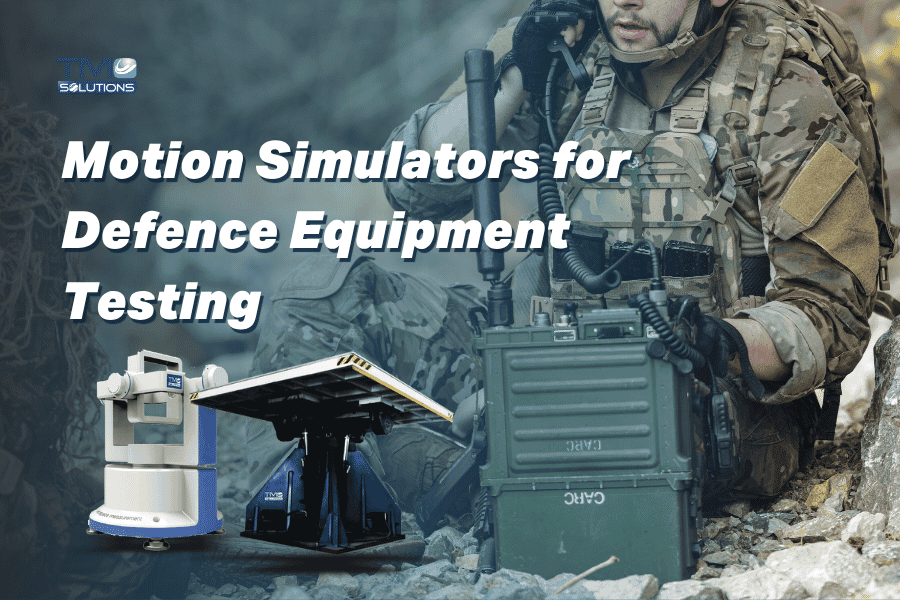
Motion Simulators for Defence Equipment Testing: What Matters Most
The most important features of motion simulators for defence equipment testing are axis configuration, angular rate and acceleration capability, positioning accuracy, payload capacity, motion profile control, repeatability, fixture compatibility, data integration, safety, and customization.
For inertial sensors, gyroscopes, accelerometers, INS, AHRS, IMUs, and stabilized platforms, engineers usually need a rate table or multi-axis motion simulator that can reproduce controlled roll, pitch, and yaw movement.
For complex defence applications such as hardware-in-the-loop testing, seeker testing, flight control validation, or platform stabilization, the system may need three-axis, five-axis, or custom motion simulation capability.
The right motion simulator should be selected around the actual equipment, test profile, payload, motion range, accuracy requirement, and integration needs — not only the number of axes.
TMC Solutions provides rate tables and motion simulators for gyroscopes, accelerometers, inertial navigation systems, and related motion-sensitive equipment, including standardized and customized solutions for demanding test requirements.
Why Motion Simulators Matter in Defence Equipment Testing
Defence equipment often operates in conditions where motion is not simple, slow, or predictable.
A vehicle may turn sharply.
A UAV may pitch, roll, and yaw during flight.
A stabilized platform may need to maintain target alignment while the base is moving.
An inertial navigation system may need to remain accurate while exposed to rotation, acceleration, vibration, temperature change, and changing orientation.
A missile, drone, or mission-critical control system may need to be tested before field trials because real tests can be expensive, limited, risky, or difficult to repeat.
This is where motion simulators and rate tables become important. They allow engineers to reproduce controlled movement in a laboratory environment so they can evaluate how defence components behave before deployment.
For defence teams, the goal is not just to rotate a product. The goal is to understand whether the product can measure, respond, stabilize, navigate, or control correctly when motion becomes part of the operating environment.
What Is a Motion Simulator for Defence Equipment Testing?
A motion simulator is a test system that reproduces controlled movement such as rotation, tilt, acceleration, or multi-axis motion.
In defence equipment testing, motion simulators are often used to evaluate:
Gyroscopes
Accelerometers
IMUs
INS
AHRS
Flight control systems
Platform stabilization devices
Seeker and tracking systems
Vehicle-mounted sensors
UAV and drone electronics
Defence electronics
Navigation and guidance-related equipment
Motion-sensitive payloads
Inertial sensor packages
Equipment clusters that must work across multiple axes
A rate table is a type of motion simulator used to provide controlled angular position, angular rate, and angular acceleration.
Single-axis, two-axis, three-axis, and higher-axis motion simulators are used depending on how complex the test requirement is.
For example, a simple gyroscope calibration may only need one axis.
An IMU or INS test may need two or three axes.
A hardware-in-the-loop simulation may require three-axis or five-axis motion to reproduce more complex operating conditions.
Motion Simulator vs Rate Table: What Is the Difference?
The terms are sometimes used together, but they are not always the same.
A rate table usually focuses on controlled angular position, rate, and acceleration.
A motion simulator can refer to a broader system that reproduces more complex movement, including multiple axes or flight-like motion profiles.
In simple terms:
| System Type | Best For | Typical Defence Use |
|---|---|---|
| Single-axis rate table | One-axis angular rate or position testing | Gyroscope testing, single-axis sensor validation |
| Two-axis rate table | Testing motion across two intersecting axes | IMU, AHRS, sensor package testing |
| Three-axis motion simulator | Roll, pitch, and yaw simulation | INS, flight control electronics, platform stabilization |
| Five-axis motion simulator | Complex HWIL and target motion simulation | Seeker-related testing, guidance-related hardware, multi-axis motion-sensitive systems |
| Motion simulator with climatic chamber | Motion testing under temperature conditions | Defence electronics, inertial systems, sensor packages exposed to thermal environments |
| Customized motion system | Application-specific motion profiles or payloads | Large, unusual, sensitive, or mission-critical defence equipment |
The right choice depends on the actual motion environment that needs to be reproduced.
Key Features Engineers Should Compare
1. Number of Axes
Axis configuration is one of the first decisions.
A single-axis rate table may be enough for basic gyroscope testing.
A two-axis system may be better for sensors that must be evaluated in different orientations.
A three-axis system can simulate roll, pitch, and yaw, which is important for INS, AHRS, flight control systems, and stabilized platforms.
More complex applications may require four-axis or five-axis motion simulation, especially when the test involves hardware-in-the-loop scenarios or target motion.
Engineers should ask:
Does the equipment need one-axis, two-axis, three-axis, or higher-axis testing?
Does the test require roll, pitch, yaw, or combined motion?
Will the system need to simulate flight dynamics or only provide calibration movement?
Is the equipment sensitive to motion in multiple axes?
Will future test programs require more axes than the current project?
Choosing too few axes can limit test coverage.
Choosing too many axes can increase complexity and cost without improving the test.
2. Angular Rate and Acceleration Capability
Defence equipment may need to respond to fast angular movement, slow precision motion, repeated movement, or rapid changes in direction.
For this reason, engineers should compare:
Maximum angular rate
Minimum controllable rate
Angular acceleration
Motion smoothness
Dynamic response
Speed stability
Direction reversal capability
Profile execution accuracy
A motion simulator used for basic calibration does not need the same dynamic capability as a system used for flight control or HWIL testing.
The motion profile should match the real operating condition as closely as possible.
3. Positioning Accuracy
Positioning accuracy matters when testing sensors, navigation systems, and stabilized platforms.
A small angular error can affect the quality of calibration data or system response measurement.
Engineers should review:
Position accuracy
Position repeatability
Resolution
Encoder performance
Servo control quality
Motion stability
Alignment accuracy
Long-term drift behaviour
For IMUs, INS, AHRS, gyroscopes, and accelerometers, accuracy and repeatability are often more important than simply achieving a high motion speed.
4. Payload Capacity
Payload is not only the weight of the device under test.
It may include:
DUT
Fixture
Mounting plate
Sensor package
Cable routing
Slip ring or electrical interface
Thermal enclosure, if used
Adapter plates
Protective structures
A motion simulator that looks suitable on paper may not perform correctly if the total moving mass is underestimated.
Payload also affects dynamic performance.
A heavier payload may reduce acceleration capability, influence servo response, or require a more robust fixture and drive system.
Before choosing a system, engineers should define the full test mass, centre of gravity, mounting orientation, and future payload needs.
5. Motion Profile Control
Defence equipment testing often requires more than simple rotation.
A useful motion simulator should be able to reproduce specific motion profiles that match the test objective.
These may include:
Constant rate motion
Step motion
Positioning sequences
Oscillation
Roll, pitch, and yaw profiles
Multi-axis movement
Flight-like motion profiles
Repeated cycles
Custom motion programs
Hardware-in-the-loop command input
The better the motion profile control, the easier it is to reproduce the test condition and collect useful engineering data.
6. Repeatability
Repeatability is essential for defence testing because engineers often need to compare:
Multiple units
Production batches
Design revisions
Calibration results
Before-and-after test data
Supplier samples
Qualification stages
If the simulator cannot repeat the same movement accurately, the data becomes harder to trust.
Engineers should compare how well the system repeats position, rate, acceleration, and full motion sequences.
7. Fixture Compatibility
Fixture design can strongly affect test accuracy.
The fixture must hold the defence component securely without introducing unwanted movement, vibration, misalignment, or resonance.
A good fixture should consider:
Mounting points
Centre of gravity
Cable routing
Sensor orientation
Alignment with the simulator axes
Stiffness
Safety margin
Access for inspection
Repeatable mounting between tests
For motion-sensitive systems, fixture alignment is not a small detail. It can directly affect calibration and test results.
8. Cable Management and Slip Ring Requirements
Many defence devices need power, signal, or data connection during motion testing.
This is especially important for:
IMUs
INS
AHRS
Flight control electronics
Sensor packages
Stabilized platforms
Active systems tested during motion
HWIL setups
Engineers should consider whether the system needs:
Slip rings
Fibre optic rotary joints
Electrical signal routing
Data communication interfaces
Power supply through rotating axes
Cable strain relief
Low-noise wiring
Shielding for sensitive signals
Poor cable management can create noise, restrict movement, damage cables, or affect the device being tested.
9. Control System and Data Integration
A motion simulator should not be viewed only as mechanical hardware.
The controller, software, interface, and data output are just as important.
Engineers should review:
Motion control software
User interface
Programmed test sequence capability
Data recording
Real-time command input
External control interfaces
Synchronization with other test systems
Safety interlocks
Alarm handling
Reporting options
For HWIL applications, integration becomes even more important because the actual hardware may need to interact with simulated motion in real time.
10. Environmental Integration
Some defence equipment must be tested under motion and temperature conditions.
For example, inertial sensors, electronics, and navigation systems may behave differently at high or low temperature.
In those cases, a rate table combined with a climatic chamber may be useful.
This allows the Unit Under Test to be exposed to high or low temperatures while motion testing is performed.
When reviewing this type of setup, engineers should consider:
Temperature range
Cooling method
Heating method
Chamber size
Table access
Cable routing
Condensation control
Thermal stability
Sensor performance over temperature
Maintenance access
Combined motion and environmental testing can be useful when the real operating condition includes both movement and temperature stress.
11. Safety and Installation Requirements
Motion simulators can involve rotating equipment, moving masses, high-speed axes, and electrical systems.
Safety should be considered early, especially for larger payloads or high-dynamic applications.
Important safety considerations include:
Emergency stop
Axis limits
Mechanical stops
Interlocks
Guarding
Payload retention
Balance requirements
Floor loading
Foundation requirements
Maintenance access
Operator training
Safe cable routing
Protective enclosure, if required
A motion simulator should be selected not only for performance, but also for safe and practical use in the customer’s lab.
12. Customization Capability
Defence testing requirements are often not standard.
The device may have an unusual shape, sensitive interface, strict mounting orientation, confidential integration requirement, or custom motion profile.
Customization may be required for:
Payload capacity
Table size
Axis configuration
Fixture design
Motion control software
Climatic chamber integration
Electrical routing
Safety guarding
Installation layout
Data output
Factory acceptance testing
Documentation requirements
This is one area where TMC can support engineering teams with both standardized and customized motion testing solutions.
Comparison Table: What Matters Most When Choosing a Defence Motion Simulator
| Feature | Why It Matters | What Engineers Should Check |
|---|---|---|
| Axis configuration | Defines what motion can be reproduced | Single-axis, two-axis, three-axis, five-axis, custom axes |
| Angular rate | Determines speed capability | Minimum rate, maximum rate, rate stability |
| Angular acceleration | Important for dynamic motion profiles | Acceleration level, response time, direction changes |
| Positioning accuracy | Critical for sensor and navigation testing | Accuracy, repeatability, resolution, encoder quality |
| Payload capacity | Affects performance and safety | DUT weight, fixture weight, centre of gravity, future payloads |
| Table size | Determines DUT and fixture compatibility | Mounting space, adapter plates, cable access |
| Motion profile control | Allows realistic test conditions | Constant rate, programmed profiles, multi-axis motion |
| Repeatability | Needed for reliable qualification and comparison | Repeatable position, rate, acceleration, and sequence execution |
| Fixture compatibility | Prevents poor data from poor mounting | Stiffness, alignment, mounting condition, safety |
| Cable management | Needed for powered or instrumented DUTs | Slip rings, wiring, shielding, power and data routing |
| Controller and software | Determines usability and integration | Test programming, external commands, data logging, reporting |
| HWIL compatibility | Supports real hardware in simulated conditions | Interface, real-time control, synchronization |
| Environmental integration | Supports motion under temperature conditions | Climatic chamber, heating, cooling, thermal access |
| Safety features | Protects operators, DUT, and equipment | Interlocks, limits, emergency stop, guarding |
| Customization | Matches non-standard defence requirements | Custom axes, fixtures, payloads, software, and installation |
When to Use Each Type of Motion Simulator
Use a Single-Axis Rate Table When
Use a single-axis rate table when the test only needs controlled rotation around one axis.
This may be suitable for:
Gyroscope testing
Single-axis accelerometer evaluation
Basic sensor calibration
Rate stability checks
Production testing of simple inertial components
A single-axis rate table can be practical when the test requirement is focused and does not need full multi-axis motion.
Use a Two-Axis Rate Table When
Use a two-axis rate table when the equipment needs to be tested in more than one orientation or when two intersecting axes are important.
This may be suitable for:
IMU testing
AHRS calibration
Small inertial sensor packages
Sensor alignment checks
Multi-orientation performance evaluation
Two-axis systems provide more flexibility than single-axis systems without the complexity of full three-axis motion.
Use a Three-Axis Motion Simulator When
Use a three-axis motion simulator when roll, pitch, and yaw must be reproduced.
This may be suitable for:
Inertial navigation systems
Flight control electronics
Platform stabilization devices
UAV electronics
Vehicle-mounted sensors
Defence navigation modules
Multi-axis sensor clusters
Three-axis testing is often useful when the component must respond correctly to realistic movement in multiple directions.
Use a Five-Axis Motion Simulator When
Use a five-axis motion simulator when the test involves more complex dynamic scenarios, such as hardware-in-the-loop simulation or target motion simulation.
This may be suitable for:
Complex guidance-related equipment
Seeker-related test environments
Multi-axis inertial systems
Sensor and target interaction testing
Advanced defence R&D programs
High-dynamic motion simulation
A five-axis system is usually selected when the test needs more than roll, pitch, and yaw alone.
Use a Motion Simulator with Climatic Chamber When
Use a rate table or motion simulator with a climatic chamber when motion-sensitive equipment must also be validated across temperature conditions.
This may be suitable for:
Defence electronics
IMUs
INS
AHRS
Sensor packages
Navigation equipment
Components used in hot, cold, or changing environments
This setup helps engineers understand whether motion performance changes under thermal stress.
Use a Customized Motion System When
Use a customized motion system when the application cannot be solved with a standard table.
This may be required when:
The DUT is large or unusually shaped
The fixture is complex
The payload is high
The motion profile is application-specific
The test needs special safety features
The system must integrate with other test equipment
The customer has unique defence qualification requirements
For many defence applications, customization is not an extra. It is often what makes the test useful.
Real Application Example: Testing a Defence Inertial Navigation Unit
A defence manufacturer needs to validate an inertial navigation unit used in a mobile platform.
The unit includes gyroscopes, accelerometers, electronics, connectors, firmware, and a mounting structure.
The engineering team needs to understand whether the unit can maintain accurate output during controlled movement.
The test objective includes:
Checking sensor response across roll, pitch, and yaw
Measuring performance during repeated angular motion
Evaluating orientation accuracy
Confirming stability under different motion profiles
Testing the unit while powered and communicating data
Reviewing whether mounting and cable routing affect performance
Comparing results across multiple units
A basic single-axis rate table may not be enough because the system is sensitive to motion in multiple axes.
A three-axis motion simulator may be more suitable because it can reproduce roll, pitch, and yaw movement in a controlled laboratory setup.
If the unit must also be tested under temperature conditions, the team may consider a rate table combined with a climatic chamber.
If the unit must interact with a real-time simulation environment, the project may require HWIL integration.
In this case, the best system is not selected by the product name alone.
It is selected by matching the test objective, axis requirement, angular rate, accuracy, payload, fixture, electrical connection, software interface, and future testing needs.
How TMC Supports Defence Motion Testing Requirements
TMC Solutions provides rate tables and motion simulators designed for testing gyroscopes, accelerometers, inertial navigation systems, and related equipment.
The product range includes solutions from single-axis rate tables to five-axis motion simulators, as well as rate tables that can be combined with climatic chambers for high and low temperature exposure.
TMC motion simulation rate tables are designed to simulate roll, pitch, and yaw movement in the laboratory. They can support testing and calibration of inertial systems, packages, or clusters that are sensitive to motion in multiple axes.
For defence and aerospace development, motion simulators can also support Hardware-In-The-Loop testing, helping reduce the time and cost associated with field trials by allowing engineers to test real hardware under simulated motion conditions.
Motion Simulators vs Other Defence Test Systems
Motion simulators are important, but they are not the only reliability test equipment used for defence applications.
Depending on the product, engineers may also need vibration, shock, SRS shock, drop, centrifuge, or environmental testing.
| Test Need | Best-Fit System Type | Why It Matters |
|---|---|---|
| Controlled roll, pitch, yaw movement | Motion simulator / rate table | Tests motion-sensitive systems, sensors, and navigation equipment |
| Gyroscope, accelerometer, IMU calibration | Rate table | Provides controlled angular position, rate, and acceleration |
| Sustained acceleration or high-G load | Centrifuge | Validates performance under constant acceleration |
| Sudden impact or mechanical shock | Shock test system | Tests resistance to defined shock pulses |
| Complex transient shock response | SRS shock test system | Evaluates response across a frequency spectrum |
| Repeated vibration | Vibration test system | Simulates dynamic fatigue and operational vibration |
| Packaging and handling impact | Drop test system | Validates transport and handling protection |
| Temperature plus motion | Rate table with climatic chamber | Tests motion-sensitive systems under thermal stress |
The best defence test setup depends on the real condition the equipment must survive or measure.
Common Mistakes When Choosing Motion Simulators for Defence Testing
Mistake 1: Choosing Only by Number of Axes
More axes are not always better.
The correct number of axes depends on the motion that needs to be reproduced and the behaviour being measured.
Mistake 2: Ignoring Payload and Centre of Gravity
Payload capacity is not just a weight limit.
The DUT, fixture, adapters, cables, and centre of gravity all affect performance and safety.
Mistake 3: Overlooking Accuracy and Repeatability
High speed is useful only if the motion is accurate and repeatable.
For inertial sensor testing, precision often matters more than maximum speed.
Mistake 4: Treating the Fixture as Secondary
Poor fixture alignment can create poor data.
The fixture must match the mounting condition and keep the equipment aligned with the simulator axes.
Mistake 5: Forgetting Data and Control Integration
For powered equipment, active sensors, and HWIL testing, the control interface and data connection are critical.
The simulator must work with the wider test environment.
Mistake 6: Not Considering Future Test Requirements
A lab may begin with one product but later need to test more complex equipment.
Future payloads, axes, motion profiles, and environmental requirements should be discussed before selecting the system.
Questions Engineers Should Prepare Before Requesting a Motion Simulator
Before contacting TMC, prepare as much of the following information as possible:
Type of defence equipment
DUT size
DUT weight
Fixture weight
Total payload
Centre of gravity
Required number of axes
Required angular rate
Required angular acceleration
Required positioning accuracy
Motion profile
Test duration
Repeatability requirement
Required temperature condition, if any
Whether the DUT must be powered during testing
Required cable or signal routing
Data acquisition requirements
HWIL integration needs
Safety requirements
Available lab space
Foundation or installation constraints
Test standard or internal qualification requirement
Future testing needs
The more clearly the requirement is defined, the easier it is to recommend the right motion simulator.
FAQ: Motion Simulators for Defence Equipment Testing
-
A motion simulator is used to reproduce controlled movement in a laboratory so engineers can test how defence equipment performs under motion. It is commonly used for inertial sensors, gyroscopes, accelerometers, IMUs, INS, AHRS, flight control systems, stabilized platforms, and motion-sensitive electronics.
-
A rate table usually provides controlled angular position, rate, and acceleration, often for sensor calibration or inertial system testing. A motion simulator can be broader and may reproduce more complex multi-axis movement, including roll, pitch, yaw, and hardware-in-the-loop motion profiles.
-
IMU testing often uses a two-axis or three-axis rate table, depending on the test requirement. The system should provide accurate angular position, angular rate, repeatability, and fixture alignment.
-
A three-axis motion simulator is required when the equipment must be tested across roll, pitch, and yaw. This is common for inertial navigation systems, flight control electronics, stabilized platforms, UAV electronics, and multi-axis sensor packages.
-
A five-axis motion simulator is usually required for more complex test environments, including advanced HWIL setups, target motion simulation, seeker-related testing, or systems that need more than roll, pitch, and yaw movement.
-
Payload capacity affects both performance and safety. Engineers must consider the DUT, fixture, adapters, cables, and mounting hardware. Underestimating payload can reduce accuracy, limit acceleration, affect repeatability, or create unsafe test conditions.
-
Positioning accuracy matters because sensors and navigation systems depend on precise motion input. If the rate table or motion simulator is not accurate, the test data may not correctly represent the behaviour of the equipment.
-
Yes. Motion simulators can be used in HWIL setups where real hardware operates with a simulated dynamic environment. This can help engineering teams test hardware, software, sensors, and control responses before field trials.
-
Yes. Some rate tables can be combined with climatic chambers so the Unit Under Test is exposed to high or low temperature while motion testing is performed. This is useful when motion-sensitive equipment must operate under environmental stress.
-
Engineers should compare axis configuration, angular rate, acceleration, positioning accuracy, repeatability, payload capacity, table size, fixture compatibility, cable routing, software control, HWIL integration, safety features, environmental options, and customization capability.
-
No. Motion simulators and rate tables are also used in aerospace, automotive, electronics, marine, UAV, space, and industrial applications. However, defence applications often require higher customization, stronger documentation, and more demanding reliability validation.
-
TMC reviews the customer’s test requirement, including DUT size, payload, axis needs, motion profile, accuracy requirement, fixture, environmental conditions, and integration needs. Based on this information, TMC can recommend a suitable rate table, motion simulator, or customized test system.
Final Recommendation
Choosing a motion simulator for defence equipment testing starts with the motion requirement, not the equipment name.
A single-axis rate table may be enough for basic gyroscope testing.
A two-axis or three-axis rate table may be better for IMU, AHRS, INS, and platform stabilization testing.
A five-axis motion simulator may be required for complex HWIL or target motion simulation.
A rate table with climatic chamber may be needed when temperature affects sensor or system performance.
A customized motion system may be the best choice when the payload, fixture, motion profile, safety requirement, or integration need does not fit a standard configuration.
For defence equipment, the right system is the one that can reproduce the required motion accurately, repeatably, and safely with the actual DUT, fixture, payload, and test profile.
Get a system recommendation from our engineering team.