
What is a Half-Sine Shock Pulse? Definition and Applications
What is a Half-Sine Shock Pulse? Definition, Applications & Testing Standards
Basic Concept and Definition of Half-Sine Shock Pulses
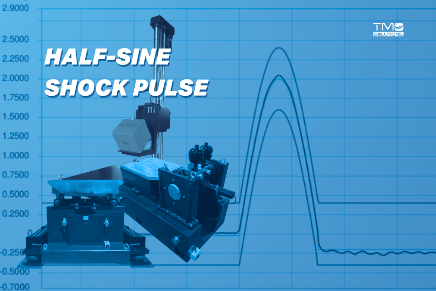
A half-sine shock pulse is a specific type of mechanical shock waveform characterized by a symmetrical arched shape that resembles the positive half of a sinusoidal wave (0 to π radians). This waveform is mathematically defined by the equation:
y(t) =A⋅sin(ωt), for 0 ≤ t ≤ T/2
where:
A = peak acceleration amplitude,
ω = angular frequency, and
T = period of the complete sine wave.
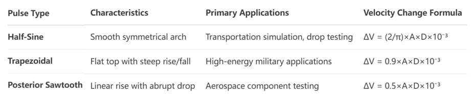
Beyond this half-period interval, the function value typically drops to zero, creating an isolated pulse event. The half-sine pulse is one of the three primary classical shock waveforms used in mechanical shock testing, alongside trapezoidal (square) and posterior sawtooth pulses.
The fundamental characteristics of a half-sine shock pulse include its smooth rise from zero to peak acceleration followed by an equally smooth return to baseline. This specific shape makes it particularly suitable for simulating many real-world shock scenarios such as product drops, vehicular shocks, or mechanical collisions where the force application and dissipation follow a similar pattern. The waveform's symmetrical nature and well-defined mathematical properties make it ideal for standardized testing and comparative analysis across different laboratories and product types.
Real-World Applications of Half-Sine Shock Testing
1. Packaging and Transportation Simulation Testing
Used in ISTA and ASTM D4169 standards to simulate:
Drops
Handling shocks
Impacts during shipping
Half-sine shock pulses are extensively used to simulate transportation environments for products and packaging systems. During transit, products may experience sudden shocks from handling, vehicular braking, or rail switching that often generate shock profiles closely approximated by half-sine waveforms. The International Safe Transit Association (ISTA) and ASTM D4169 standards incorporate half-sine shock testing to evaluate packaging protective performance and product durability under these conditions. By subjecting products to controlled half-sine shocks at specified acceleration levels and durations, engineers can identify vulnerable components and improve packaging designs to prevent damage during distribution.
Learn more about ISTA packaging testing
2. Military and Aerospace Equipment Validation
Referenced in MIL-STD-810H for:
Weapons recoil
Hard landings
Launch loads
Testing ranges often exceed 100g, with sub-millisecond pulse durations.
Military and aerospace equipment must withstand high-shock scenarios such as weapons recoil, ejection seat deployment, projectile launches, or hard landings. The MIL-STD-810H standard specifically recommends half-sine shock testing for these applications due to its ability to replicate high-energy transient events commonly encountered in defense operations. The waveform's characteristics make it suitable for testing everything from delicate avionics to ruggedized field equipment, ensuring they remain operational after exposure to severe shock forces. These tests typically involve higher acceleration levels (often exceeding 100g) and shorter durations compared to commercial product testing.
See also Advancing Defense Testing with TMC Shock Systems
3. Automotive Electronics Reliability Assessment
Aligned with ISO 16750-3, used for:
Simulating pothole & crash-induced shocks
Validating airbag controllers, ECUs, ABS modules
The ISO 16750-3 standard governing road vehicle electronic equipment testing extensively utilizes half-sine shock pulses to verify component durability in automotive environments. Automotive electronics may experience shocks from pothole encounters, curb strikes, or collision events that generate half-sine-like acceleration profiles. By subjecting electronic control units, sensors, and infotainment systems to standardized half-sine shock tests, manufacturers can identify design weaknesses, solder joint failures, or component mounting issues before vehicles reach production. These tests are particularly crucial for safety-critical systems like airbag controllers, anti-lock braking systems, and power steering modules.
4. Consumer Electronics Durability Verification
Half-sine pulses simulate:
Drops on phones, tablets, laptops
Durability of internal components (e.g. PCBs, connectors)
Consumer electronics manufacturers use half-sine shock testing to simulate accidental drops and shocks that devices may experience during everyday use. Mobile phones, tablets, laptops, and wearables are subjected to half-sine shocks at various orientations to evaluate structural integrity, screen durability, and internal component security. The test parameters (typically 500-1500g acceleration with 0.5-2ms duration) are derived from actual drop test measurements onto different surfaces. This application helps identify failure points like PCB trace cracks, connector detachment, or housing fractures, leading to improved product designs that better withstand real-world use conditions.
How Half-Sine Shock Is Measured
Key Measurement Parameters
Peak Acceleration (g)
Pulse Duration (ms)
Velocity Change (ΔV):
ΔV = 2/π × A × D × 10⁻³
Accurate measurement of half-sine shock pulses requires careful attention to three primary parameters: peak acceleration, pulse duration, and velocity change. Peak acceleration represents the maximum amplitude reached during the pulse, typically measured in g-force units (where 1g=9.8 m/s²). Pulse duration refers to the time interval between the initial and final points where the signal exceeds 10% of the peak amplitude. Velocity change (ΔV) represents the integral of acceleration over time and provides information about the total energy transferred during the shock event.
For half-sine pulses, the velocity change can be calculated using the formula:
ΔV = 2/π × A × D × 10⁻³
where A is the peak acceleration (m/s²) and D is the pulse duration (seconds).
Instrumentation and Data Acquisition
Piezoelectric accelerometers (DC to 10kHz bandwidth)
16-bit+ data acquisition
High sampling rate (10–20x highest frequency)
Modern shock measurement systems typically employ piezoelectric accelerometers with appropriate frequency response characteristics to capture half-sine pulses accurately. These sensors must have a broad frequency bandwidth (typically DC to 10kHz or higher) to ensure proper reproduction of the transient signal without phase distortion or amplitude attenuation. Signal conditioning equipment including amplifiers and anti-aliasing filters are essential for preparing the signal for digital acquisition. Data acquisition systems should sample at rates sufficiently high to capture the transient detail (typically 10-20 times the highest frequency component of interest) and must have adequate resolution (16-bit or better) to measure both high and low amplitude components accurately.
Measurement Uncertainty Sources
Sensor calibration
Fixture design (avoid resonances)
Signal conditioning
Proper filtering and analysis techniques
Several factors contribute to measurement uncertainty in half-sine shock testing, including sensor calibration errors, fixturing resonances, signal conditioning artifacts, and data processing limitations. Accelerometer characteristics such as transverse sensitivity, base strain sensitivity, and temperature effects can introduce measurement errors. Fixture design imperfections may cause resonances that distort the applied shock pulse. Digital signal processing introduces uncertainties related to sampling rate, anti-aliasing filter characteristics, and algorithm implementation. A comprehensive uncertainty analysis following guidelines such as those in GB/T 27418 or JJG 1174 is essential for producing reliable and reproducible test results.
Generating Half-Sine Pulses in the Lab
Shock Pulse Generation Techniques
Pneumatic Systems: compressed air + programmable material
Electrodynamic Shakers: software-controlled
Free-Fall Drop Testers: impact onto deformable surfaces
Half-sine shock pulses are typically generated using specially designed shock testing machines that can be categorized as pneumatic, electrodynamic, or free-fall systems. Pneumatic shock testers use compressed air to propel a shock hammer against a programmer material that shapes the shock into a half-sine waveform. Electrodynamic shakers can generate half-sine pulses through sophisticated waveform control algorithms but are limited in their energy capacity for high-force shocks. Free-fall drop testers create half-sine pulses by dropping a test item onto a programmed shock surface that deforms in a controlled manner to produce the desired waveform. The programmer material (often lead, rubber, or custom polymers) and its deformation characteristics primarily determine the resulting pulse shape and duration.
Waveform Verification and Control
Real-time waveform comparison
±10% peak G, ±20% duration tolerance
Pre- and post-compensation to match target waveform
Maintaining waveform integrity during half-sine shock testing requires real-time monitoring and adjustment of the shock parameters. Modern shock control systems use closed-loop feedback mechanisms that compare the measured pulse with the target specification and make adjustments to subsequent shocks. The verification process involves checking that the entire measured pulse falls within the tolerance boundaries specified by relevant standards (typically ±10% for amplitude and ±20% for duration). Special attention must be paid to the rising edge of the pulse, as this portion most significantly affects the product's response. Pre-compensation and post-compensation techniques are often employed to achieve the desired waveform, particularly when testing with complex fixtures or high-mass specimens.
Practical Measurement Tips for Engineers
Fixture Design and Mounting Considerations
Fixture mass ≥ 5× specimen mass
Use stud-mounted accelerometers for better fidelity
Minimize resonant coupling and mounting errors
Proper fixture design is critical for accurate half-sine shock testing. The fixture should have a mass at least five times greater than the test specimen to minimize interactions that could distort the shock pulse. Fixtures must be designed with **sufficient stiffness** to ensure uniform energy transmission without significant resonance effects below the frequency range of interest. Accelerometers should be mounted as close as possible to the shock point using stud mounting rather than adhesive or magnetic mounts whenever possible, as these provide better frequency response characteristics. For lightweight specimens, the mass of the accelerometer itself may affect the system's dynamics, requiring compensation in measurement calculations.
See Shock fixture design best practice for reliable test results
Calibration and System Verification
Annual calibration to national standards
Reference accelerometer checks before critical tests
Full system verification before introducing DUTs
Regular calibration of the entire measurement chain—from accelerometer to data acquisition system—is essential for reliable results. Accelerometers should be calibrated annually using a primary standard shock calibration system that provides traceability to national standards. The complete system should be verified before critical tests using a reference accelerometer with known calibration characteristics. System verification should include checks for frequency response, linearity, and transverse sensitivity effects. During testing, a pre-test verification with a reference mass should be conducted to confirm that the shock system is producing the specified pulse within acceptable tolerances before introducing actual test specimens.
Data Analysis and Interpretation
Time-domain waveform analysis
Shock Response Spectrum (SRS)
Low-pass filtering (cutoff ≈ 5–10× 1/pulse duration)
When analyzing half-sine shock data, engineers should examine both the time-domain waveform and the shock response spectrum (SRS) to fully understand the potential effects on the test item. The time-domain analysis confirms that the input pulse meets specification requirements, while the SRS reveals how different frequency components within the test item would respond to the shock. Signal processing should include appropriate filtering to remove noise without distorting the pulse characteristics, typically using a low-pass filter with a cutoff frequency set to 5-10 times the inverse of the pulse duration. Velocity change should be calculated both by integration of the measured acceleration signal and by the theoretical formula to identify any significant discrepancies that might indicate measurement problems.
Standards for Half-Sine Shock Testing
International Testing Standards:
IEC 60068-2-27: electronics shock testing
MIL-STD-810H: defense/military
ISO 16750-3: automotive
ASTM D4169: packaging transport
Half-sine shock testing is governed by several international standards that specify precise requirements for pulse shape, tolerances, and test procedures. The IEC 60068-2-27 standard establishes basic guidelines for shock testing of electronic equipment, defining acceptable tolerances for half-sine pulses and specifying testing procedures. MIL-STD-810H provides detailed guidance for environmental engineering considerations and tailors half-sine shock testing to military applications. ISO 16750-3 addresses the specific needs of automotive electronic components, while ASTM D4169 covers packaging testing for distribution environments. Each standard defines specific test levels, durations, and orientations appropriate for their respective applications.
Compliance and Reporting Requirements
Calibration certificates
Pulse waveform graphs
Environmental condition logs
ISO 17025-compliant reports
To demonstrate compliance with shock testing standards, laboratories must provide comprehensive test documentation including complete system calibration records, waveform verification data, and detailed descriptions of the test setup. Reports typically include graphs showing the measured pulse against tolerance limits, tabular data of key parameters (peak acceleration, duration, velocity change), and analysis of any deviations from the specified pulse shape. The test report must also document environmental conditions (temperature, humidity), specimen configuration, and any anomalies observed during testing. Laboratories accredited under ISO 17025 must follow strict quality assurance procedures to ensure the validity of their test results.

Table: Common Half-Sine Shock Test Levels by Application
The Future of Half-Sine Shock Testing
As product designs become more compact and integrated, testing evolves too:
Simulation + physical hybrid validation
High-bandwidth wireless sensors
AI-assisted waveform prediction & fault detection
Half-sine shock pulse testing remains a fundamental methodology for evaluating product durability across numerous industries. Its continued relevance stems from its ability to approximate real-world shock events with a simple, reproducible waveform that can be precisely specified and controlled. As products become more complex and miniaturized, half-sine shock testing continues to evolve with improved control systems, more sophisticated measurement techniques, and better understanding of material responses to mechanical shock.
Future developments in half-sine shock testing will likely include more sophisticated simulation techniques that combine physical testing with computational models, allowing for more comprehensive assessment of product durability. Advances in sensor technology including higher frequency response capabilities and wireless measurement systems will enable more accurate data collection from complex assemblies. Additionally, the integration of machine learning algorithms for waveform optimization and fault prediction represents an emerging frontier in shock testing technology. These advancements will continue to make half-sine shock testing an indispensable tool for product development and validation across the engineering spectrum.
Ready to Upgrade Your Shock Testing Setup?
TMC Solutions provides a wide range of shock test systems that deliver precise, repeatable half-sine pulses — compliant with global standards and fully customizable to your product specs.
📞 Contact our engineers today to find the right system for your lab.